OSIRIS Analyser Towers
OSIRIS has a set of analyser towers with an unusual motion control setup. The purpose of the analyser towers is to focus beam from the sample onto a detector. The towers are motion-controlled to allow this focus to be adjusted.
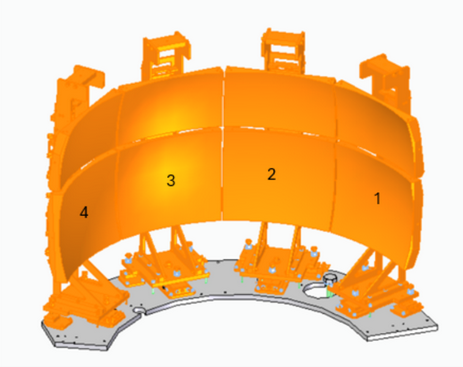
There are 4 analyser towers in total; these are labelled Towers 4, 3, 2, 1 looking left-to-right from the sample position. Each tower has two plates, an upper and a lower plate, which can drive independently.
See also
User documentation and maintenance documentation for this system in
\\isis\shares\ISIS_Experiment_Controls\Manuals\OSIRIS_Analyser_towers
Setup notes
This setup is unusual in that only two galil axes are used at a time (always an upper/lower pair for one tower). To control other towers, the corresponding motors will be physically unplugged and a new tower plugged in to the Galil controller.
After plugging in a new tower, the motors must be homed before the positions are meaningful
All axes are open loop - there are physically no encoders present.
The motion is not fully reliable. During commissioning, drift (loss of motor steps) was observed on various motors. As there are no encoders present, the only remedy for this is to rehome regularly.
Homing is set up to physically home in the positive direction, to the upper limit switch.
This represents maximum upwards tilt of the analysers
However, because the limit switches were wired the wrong way, this actually uses the
Home_RevLimit.gmchoming routine, andDIRis swapped at the motor record level to “Reverse”.
For Galil settings used during commissioning, see here.
Commissioning positions
Commissioning was done against a set of “reference” positions, checked using a surveying setup (by Accelerator engineering group). The reference positions represent the positions “as designed” to focus beam onto the detector. Limit switch positions are set to give approx +/- 1 degree of motion from the reference/design position.
Tower |
Upper limit switch |
Reference position |
Lower limit switch |
|---|---|---|---|
T4 Lower |
0 |
-0.90 |
-2.38 |
T4 Upper |
0 |
-1.60 |
-2.60 |
T3 Lower |
0 |
-1.02 |
-2.07 |
T3 Upper |
0 |
-0.97 |
-2.10 |
T2 Lower |
0 |
-1.04 |
-1.96 |
T2 Upper |
0 |
-0.87 |
-2.14 |
T1 Lower |
0 |
-1.20 |
-2.25 |
T1 Upper |
0 |
-1.10 |
-1.99 |
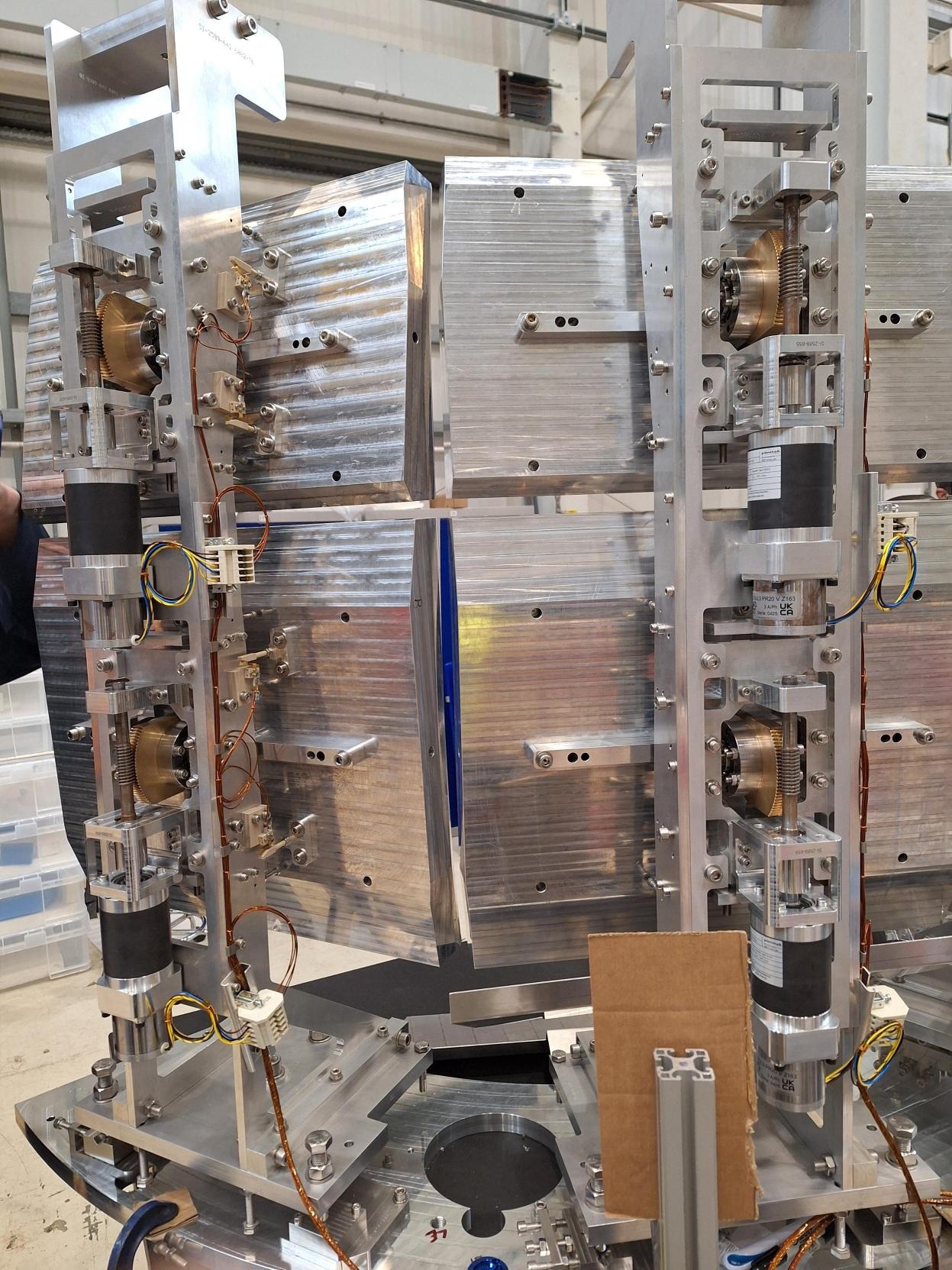
This photo shows the motion setup from the back (T1 and T2 shown):