Exercise 1 - Parameters, Drivers, Components
Introduction to Reflectometry and Specific Terminology
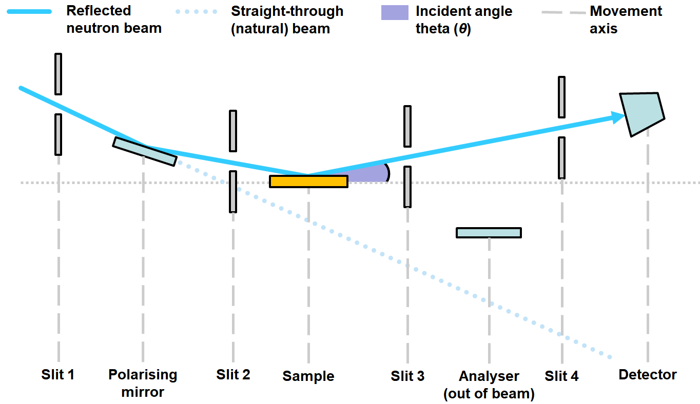
Fundamentally, the Reflectometry Config defines a geometry model of the beamline, which we use to calculate relative positions for each axis in the model based on the current beam path. We think about this model in 3 layers:
Driversare wrappers responsible for talking to the low-level motor axes which report their positions in coordinates relative to the Natural Beam, i.e. the straight beam as it enters the blockhouse (dotted blue line in the diagram above)Parametersare high level parameters relative to the current (bounced) beam (solid blue line above). These provide an abstraction so the users do not have to worry about specific offsets as all values they interact with are relative to the reflected beam. They also provide functionality which lets you enter a setpoint but not action it until you press a separate action (“move”) button, as opposed to setting a value as soon as you hit enter on an OPI text box as is the behaviour everywhere els. (This was an explicit requirement)Componentsare the middle layer geometry nodes. This layer is responsible for translating between the two different sets of coordinates mentioned above. Each component represents one node of interaction with the beam e.g. a Slit or the Sample Stack.
Going forward, whenever any of these 3 terms are used, they will be referring to the definitions above.
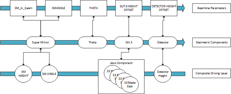
In the reflectometry config, we define a list of items for each of these 3 layers. The items in this list must appear in the order in which they appear along the physical beamline as changes in one component trigger changes downstream only. These lists are packaged into a single Beamline object, which coordinates everything at the top level. Here is a diagram representing at an abstract level what the beamline model may look like internally:
To Note:
Parameters/Drivers have a many-to-one relationship to Components
Parameters and Drivers do not have to be a one-to-one match, even though often this is the case (like a height offset parameter on the POLREF bench will equally displace front and back height jacks).
The config.py file
In the following exercise, we will add a single item to the reflectometry configuration, a Supermirror, complete with Parameters and Drivers. Before we start making changes, let’s review the content of the blank config in front of you:
from ReflectometryServer.beamline import Beamline
from ReflectometryServer.config_helper import (
    add_mode,
    get_configured_beamline,
)


def get_beamline(macros: dict[str, str]) -> Beamline:
    #########################
    # FIXED BEAMLINE VALUES #
    #########################

    # Modes
    _nr = add_mode("NR")

    ##############################
    # BEAMLINE MODEL STARTS HERE #
    ##############################

    return get_configured_beamline()
The various imports from
ReflectometryServerare the items used below. Any classes or helper methods needed to construct the model of the beamline is within this namespace.def get_beamline: While the python config file gives you tremendous freedom to include arbitrary python code, this is the one method we expect to be here as the reflectometry server calls it on config load. It should return an object of typeBeamlineThe
fixed beamline valueswill contain variables and things which do not change. For example, the distances between components.The
beamline modeldescribes the actual beamline, in order, from the beam entry point to the detectors._nr = add_mode("NR"): Modes are “presets” used to define which devices are in use & should automatically track depending on the type of experiment being run. At least one mode should be specified. This version has the underscore_at the front because at present the variable is not used, and PyRight requires the variable to be used, but it accepts one with an underscore at the front.
Exercise 1
The first thing to add to our configuration is the NATURAL_ANGLE as per here. This defines the angle of movement of the physical components relative to the natural beam which defines our coordinate system, i.e. the angle between the dotted blue line and the dotted grey lines above. Usually this is 90 + 1.5 for TS1, and 90 + 2.3 for TS2 instruments. However, in this training course for now we will assume that the natural beam is level to the floor for simplicity.
The constants which need to be named according to the interactions above do need to be set somewhere. This could be as a set of constants in another file, or simply a block before the definition for get_beamline, which is what will be used here. For the training, please set NATURAL_ANGLE to 90.
This is a fixed beamline parameter, so can be set as a constant value in the FIXED BEAMLINE VALUES section.
def get_beamline(macros: Dict[str, str]) -> Beamline:
    #########################
    # FIXED BEAMLINE VALUES #
    #########################

    # Constants
    add_constant(BeamlineConstant("NATURAL_ANGLE", NATURAL_ANGLE, "The angle between the natural beamline and our coordinate system"))

    # Modes
    _nr = add_mode("NR")
Note that add_constant is in the ReflectometryServer.config_helper library, while BeamlineConstant needs to be imported from the ReflectometryServer.beamline_constant library.
The first item on our imagined reflectometer is going to be a supermirror. This supermirror will have a few things that need to be added.
1. Add a constant for the distance
The supermirror will have a distance from the beam entry point, and this will be constant. Add it in a similar way to the previous constant, using SM_Z as a name, and a value of 20.0.
2. Add the supermirror component
The supermirror is considered a component within the beam line model, see above for the definition of this. The generic code for adding a component is as follows:
component = add_component(Component("comp_name", PositionAndAngle(Y, Z, Angle)))
add_component is in ReflectometryServer.config_helper, Component is in ReflectometryServer.components, and PositionAndAngle is in ReflectometryServer.geometry.
There are different subclasses of Components:
- Component just tracks the beam path in height
- TiltingComponent tracks the beam path in height and angle
- ReflectingComponent tracks the in height and angle and can also change the path of the beam for components further downstream
This will be a ReflectingComponent, as it can impact on the direction of the beam. It can be added using the add_component helper method shown above. This will need a name and a geometry setup, in this case a PositionAndAngle setup will be suitable, setting Y to 0, Z to SM_Z, and Angle to NATURAL_ANGLE. Don’t forget to import this from ReflectometryServer.components
3. Add parameters for the supermirror
Our supermirror has two things which can be varied, its height, and its angle. Each of these will need a parameter to interact with them. The generic code for adding a parameter is as follows:
add_parameter(AxisParameter("param_name", component, ChangeAxis.[Axis parameter], "description of parameter"))
add_parameter is in ReflectometryServer.config_helper, AxisParameter is in ReflectometryServer.parameters, and ChangeAxis is in ReflectometryServer.geometry.
ChangeAxis is used to link a given AxisParameter to a given IocDriver. For more information on the different options for AxisParameter, see here
Here, the angle, to be called SMANGLE, will be of the type ANGLE and the height, to be called SMOFFSET, of type POSITION
Note that you need to name parameters according to a certain standard in order to be able to view them readily in the reflectometry OPIs. That naming makes the use of a description, which will appear as a tooltip in the GUI which can be extremely useful.
4. Add drivers for the supermirror
Those items which can be varied here will need a driver as well, although that isn’t always the case for every parameter. The generic code for adding a driver is as follows:
add_driver(IocDriver(component, ChangeAxis.[Axis parameter], MotorPVWrapper("MOT:MTRXXXX")))
Don’t forget to add the imports. add_driver is in ReflectometryServer.config_helper, IocDriver is in ReflectometryServer.ioc_driver, and MotorPVWrapper is in ReflectometryServer.pv_wrapper
MTRXXXX should be replaced with the appropriate motor axis. In this case, they should have been set up as MTR0207 for the angle, and MTR0206 for the height (which is still has an Axis Parameter of POSITION.
To Test
Once you are done making changes, you can load the updated config by restarting the REFL_01 IOC.
On the Front Panel tab, the SM Angle value should now be visible. Don’t worry about the rest of the disconnected items, they will be added in as you progress through the exercises.
You should be able to see 2 parameters in the Collimation Plane Parameters tab, that, when set, will move the appropriate Galil axes. If you hover the parameter names the description should appear in the tool tip.
You should also be able to see 2 constants in the Constants tab.
Troubleshooting:
The Reflectometry server gets stuck Initialising - Likely trying to monitor a PV that does not exist, check the parameters on your IocDrivers
The Reflectometry server reports an Error status! - There is an error somewhere in your config file: Check the log in
/Instrument/var/logs/ioc/REFL_01_<current date>.logfor stack tracesParameter is not showing up! - Check you have defined the right ChangeAxes, if not they may show in “Other Parameters” instead.
Parameter is there but I can’t set it! - Check you can move the motors in question from the low motor table. If so, check the parameter you are setting and the IocDriver for the Galil axis have matching ChangeAxes
Solution
Should you have trouble the following is what the code could look like
from ReflectometryServer.beamline import Beamline
from ReflectometryServer.beamline_constant import BeamlineConstant
from ReflectometryServer.components import (
    ReflectingComponent,
)
from ReflectometryServer.config_helper import (
    add_component,
    add_constant,
    add_driver,
    add_mode,
    add_parameter,
    get_configured_beamline,
)
from ReflectometryServer.geometry import ChangeAxis, PositionAndAngle
from ReflectometryServer.ioc_driver import IocDriver
from ReflectometryServer.parameters import AxisParameter
from ReflectometryServer.pv_wrapper import MotorPVWrapper

# Beamline Constants
NATURAL_ANGLE = 90
SM_Z = 20.0


def get_beamline(macros: dict[str, str]) -> Beamline:
    #########################
    # FIXED BEAMLINE VALUES #
    #########################

    # Constants
    add_constant(
        BeamlineConstant(
            "NATURAL_ANGLE",
            NATURAL_ANGLE,
            "The difference between the beam and straight through",
        )
    )
    add_constant(BeamlineConstant("SM_Z", SM_Z, "The distance to the supermirror"))

    # Modes
    _nr = add_mode(
        "NR"
    )  # Using underscre to pass pyright as mode has to be created but is not used

    ##############################
    # BEAMLINE MODEL STARTS HERE #
    ##############################

    # Mirror
    mirror_comp = add_component(
        ReflectingComponent("Mirror", PositionAndAngle(0, SM_Z, NATURAL_ANGLE))
    )
    add_parameter(
        AxisParameter(
            "SMANGLE",
            mirror_comp,
            ChangeAxis.ANGLE,
            description="Angle of the Supermirror",
        )
    )
    add_parameter(
        AxisParameter(
            "SMOFFSET",
            mirror_comp,
            ChangeAxis.POSITION,
            description="Vertical Position of the Supermirror",
        )
    )
    add_driver(IocDriver(mirror_comp, ChangeAxis.ANGLE, MotorPVWrapper("MOT:MTR0207")))
    add_driver(
        IocDriver(mirror_comp, ChangeAxis.POSITION, MotorPVWrapper("MOT:MTR0206"))
    )

    return get_configured_beamline()